

Counters
A special type of sequential circuit used to count the pulse is known as a counter, or a collection of flip flops where the clock signal is applied is known as counters.
The counter is one of the widest applications of the flip flop. Based on the clock pulse, the output of the counter contains a predefined state. The number of the pulse can be counted using the output of the counter.
Truth Table

There are the following types of counters:
- Asynchronous Counters
- Synchronous Counters
Asynchronous or ripple counters
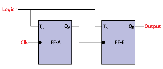
The Asynchronous counter is also known as the ripple counter. Below is a diagram of the 2-bit Asynchronous counter in which we used two T flip-flops. Apart from the T flip flop, we can also use the JK flip flop by setting both of the inputs to 1 permanently. The external clock pass to the clock input of the first flip flop, i.e., FF-A and its output, i.e., is passed to clock input of the next flip flop, i.e., FF-B.
Block Diagram


Signal Diagram

Operation
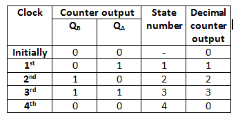
- Condition 1: When both the flip flops are in reset condition.
Operation: The outputs of both flip flops, i.e., QA QB, will be 0. - Condition 2: When the first negative clock edge passes.
Operation: The first flip flop will toggle, and the output of this flip flop will change from 0 to 1. The output of this flip flop will be taken by the clock input of the next flip flop. This output will be taken as a positive edge clock by the second flip flop. This input will not change the second flip flop’s output state because it is the negative edge triggered flip flop.
So, QA = 1 and QB = 0 - Condition 3: When the second negative clock edge is applied.
Operation: The first flip flop will toggle again, and the output of this flip flop will change from 1 to 0. This output will be taken as a negative edge clock by the second flip flop. This input will change the second flip flop’s output state because it is the negative edge triggered flip flop.
So, QA = 0 and QB = 1. - Condition 4: When the third negative clock edge is applied.
Operation: The first flip flop will toggle again, and the output of this flip flop will change from 0 to 1. This output will be taken as a positive edge clock by the second flip flop. This input will not change the second flip flop’s output state because it is the negative edge triggered flip flop.
So, QA = 1 and QB = 1 - Condition 5: When the fourth negative clock edge is applied.
Operation: The first flip flop will toggle again, and the output of this flip flop will change from 1 to 0. This output will be taken as a negative edge clock by the second flip flop. This input will change the output state of the second flip flop.
So, QA = 0 and QB = 0
Synchronous counters
In the Asynchronous counter, the present counter’s output passes to the input of the next counter. So, the counters are connected like a chain. The drawback of this system is that it creates the counting delay, and the propagation delay also occurs during the counting stage. The synchronous counter is designed to remove this drawback.
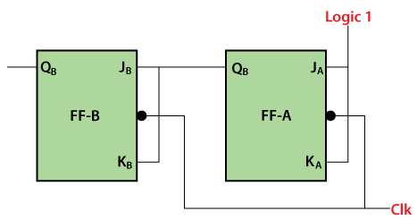
In the synchronous counter, the same clock pulse is passed to the clock input of all the flip flops. The clock signals produced by all the flip flops are the same as each other. Below is the diagram of a 2-bit synchronous counter in which the inputs of the first flip flop, i.e., FF-A, are set to 1. So, the first flip flop will work as a toggle flip-flop. The output of the first flip flop is passed to both the inputs of the next JK flip flop.
Logical Diagram


Signal Diagram

Operation
- Condition 1: When both the flip flops are in reset condition.
Operation: The outputs of both flip flops, i.e., QA QB, will be 0.
So, QA = 0 and QB = 0 - Condition 2: When the first negative clock edge passes.
Operation: The first flip flop will be toggled, and the output of this flip flop will be changed from 0 to 1. When the first negative clock edge is passed, the output of the first flip flop will be 0. The clock input of the first flip flop and both of its inputs will set to 0. In this way, the state of the second flip flop will remain the same.
So, QA = 1 and QB = 0 - Condition 2: When the second negative clock edge is passed.
Operation: The first flip flop will be toggled again, and the output of this flip flop will be changed from 1 to 0. When the second negative clock edge is passed, the output of the first flip flop will be 1. The clock input of the first flip flop and both of its inputs will set to 1. In this way, the state of the second flip flop will change from 0 to 1.
So, QA = 0 and QB = 1 - Condition 2: When the third negative clock edge passes.
Operation: The first flip flop will toggle from 0 to 1, but at this instance, both the inputs and the clock input set to 0. Hence, the outputs will remain the same as before.
So, QA = 1 and QB = 1 - Condition 2: When the fourth negative clock edge passes.
Operation: The first flip flop will toggle from 1 to 0. At this instance, the inputs and the clock input of the second flip flop set to 1. Hence, the outputs will change from 1 to 0.
So, QA = 0 and QB = 0
TYPES
Ripple Counter
Ripple counter is a special type of Asynchronous counter in which the clock pulse ripples through the circuit. The n-MOD ripple counter forms by combining n number of flip-flops. The n-MOD ripple counter can count 2n states, and then the counter resets to its initial value.
Features of the Ripple Counter:
- Different types of flip flops with different clock pulse are used.
- It is an example of an asynchronous counter.
- The flip flops are used in toggle mode.
- The external clock pulse is applied to only one flip flop. The output of this flip flop is treated as a clock pulse for the next flip flop.
- In counting sequence, the flip flop in which external clock pulse is passed, act as LSB.
Based on their circuitry design, the counters are classified into the following types:
Up Counter
The up-counter counts the states in ascending order.
Down Counter
The down counter counts the states in descending order.
Up-Down Counter
The up and down counter is a special type of bi-directional counter which counts the states either in the forward direction or reverse direction. It also refers to a reversible counter.
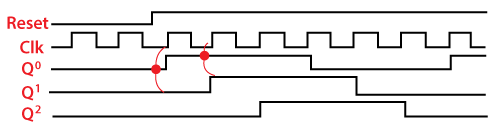
Binary Ripple Counter
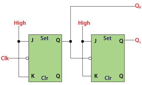
A Binary counter is a 2-Mod counter which counts up to 2-bit state values, i.e., 22 = 4 values. The flip flops having similar conditions for toggling like T and JK are used to construct the Ripple counter. Below is a circuit diagram of a binary ripple counter.
In the circuit design of the binary ripple counter, two JK flip flops are used. The high voltage signal is passed to the inputs of both flip flops. This high voltage input maintains the flip flops at a state 1. In JK flip flops, the negative triggered clock pulse use.

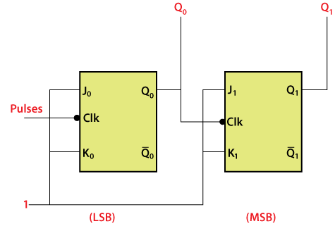
The outputs Q0 and Q1 are the LSB and MSB bits, respectively. The truth table of JK flip flop helps us to understand the functioning of the counter.

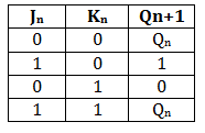
When the high voltage to the inputs of the flip flops, the fourth condition is of the JK flip flop occurs. The flip flops will be at the state 1 when we apply high voltage to the input of the flip-flop. So, the states of the flip flops passes are toggled at the negative going end of the clock pulse. In simple words, the flip flop toggle when the clock pulse transition takes place from 1 to 0.

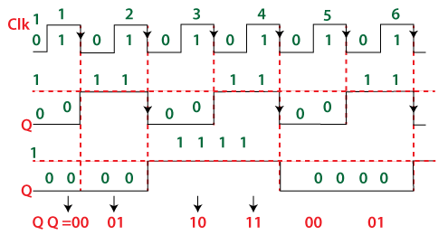
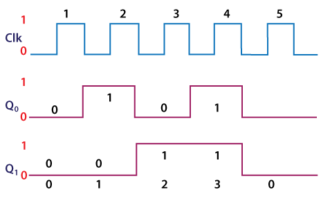
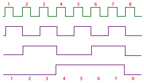
The state of the output Q0 change when the negative clock edge passes to the flip flop. Initially, all the flip flops are set to 0. These flip flop changes their states when the passed clock goes from 1 to 0. The JK flip flop toggles when the inputs of the flip flops are one, and then the flip flop changes its state from 0 to 1. For all the clock pulse, the process remains the same.

The output of the first flip flop passes to the second flip flop as a clock pulse. From the above timing diagram, it is clear that the state of the second flip flop is changed when the output Q0 goes transition from 1 to 0. The outputs Q0 and Q1 treat as LSB and MSB. The counter counts the values 00, 01, 10, 11. After counting these values, the counter resets itself and starts counting again from 00, 01, 10, and 1. The count values until the clock pulses are passed to J0K0 flip flop.
Ring Counter
A ring counter is a special type of application of the Serial IN Serial OUT Shift register. The only difference between the shift register and the ring counter is that the last flip flop outcome is taken as the output in the shift register. But in the ring counter, this outcome is passed to the first flip flop as an input. All of the remaining things in the ring counter are the same as the shift register.
In the Ring counter
No. of states in Ring counter = No. of flip-flop used
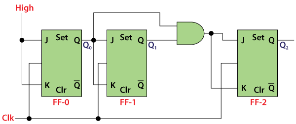
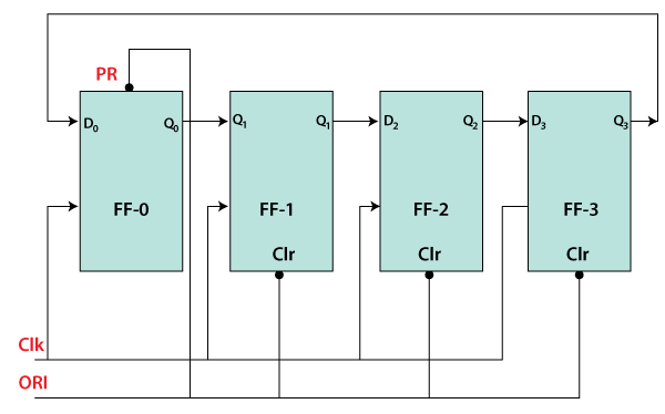
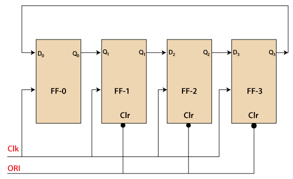
Below is the block diagram of the 4-bit ring counter. Here, we use 4 D flip flops. The same clock pulse is passed to the clock input of all the flip flops as a synchronous counter. The Overriding input(ORI) is used to design this circuit.
The Overriding input is used as clear and pre-set.

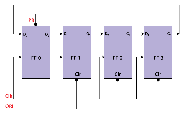
The output is 1 when the pre-set set to 0. The output is 0 when the clear set to 0. Both PR and CLR always work in value 0 because they are active low signals.
- PR = 0, Q = 1
- CLR = 0, Q = 0
These two values(always fixed) are independent with the input D and the Clock pulse (CLK).
Working
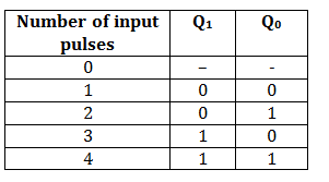
The ORI input is passed to the PR input of the first flip flop, i.e., FF-0, and it is also passed to the clear input of the remaining three flip flops, i.e., FF-1, FF-2, and FF-3. The pre-set input set to 0 for the first flip flop. So, the output of the first flip flop is one, and the outputs of the remaining flip flops are 0. The output of the first flip flop is used to form the ring in the ring counter and referred to as Pre-set 1.

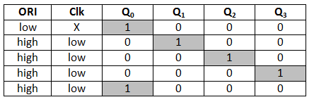
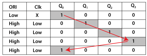
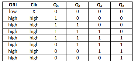
In the above table, the highlighted 1’s are pre-set 1.
The Pre-set 1 is generated when
- ORI input set to low, and that time the Clk doesn’t care.
- When the ORI input set to high, and the low clock pulse signal is passed as the negative clock edge triggered.
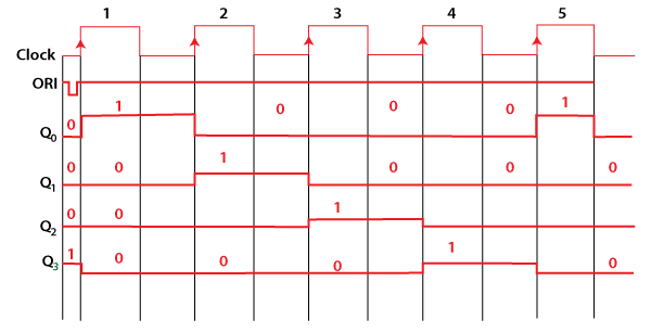
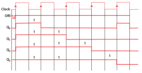
A ring forms when the pre-set 1 is shifted to the next flip-flop at each clock pulse.
So, 4-bit counter, 4 states are possible which are as follows:
- 1 0 0 0
- 0 1 0 0
- 0 0 1 0
- 0 0 0 1
Types of Ring Counter
The ring counter is classified into two parts which are as follows:
Straight Ring Counter
The Straight Ring Counter refers to as One hot Counter. The outcome of the last flip-flop is passed to the first flip-flop as an input. In the ring counter, the ORI input is passed to the PR input for the first flip flop and to the clear input of the remaining flip flops.
Note: The straight ring counter circulates the single 1 (or 0) bit around the ring.
Logic Diagram

Truth Table

Signal Diagram

Twisted Ring Counter
The Twisted Ring Counter refers to as a switch-tail ring Counter. Like the straight ring counter, the outcome of the last flip-flop is passed to the first flip-flop as an input. In the twisted ring counter, the ORI input is passed to all the flip flops as clear input.
Note: The twisted ring counter circulates a stream of 1’s followed by 0 around the ring.
Logic Diagram

Truth Table

Signal Diagram

Johnson Counter
The Johnson counter is similar to the Ring counter. The only difference between the Johnson counter and the ring counter is that the outcome of the last flip flop is passed to the first flip flop as an input. But in Johnson counter, the inverted outcome Q’ of the last flip flop is passed as an input. The remaining work of the Johnson counter is the same as a ring counter. The Johnson counter is also referred to as the Creeping counter.
In Johnson counter
- No. of states in Johnson counter = No. of flip-flop used
- Number of used states=2n
- Number of unused states=2n – 2*n
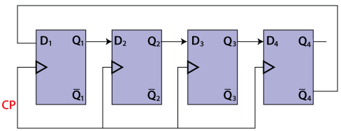
Below is the diagram of the 4-bit Johnson counter. Like Ring counter, four D flip flops are used in the 4-bit Johnson counter, and the same clock pulse is passed to all the input of the flip flops.

Truth Table
| CP | Q1 | Q2 | Q3 | Q4 |
|---|---|---|---|---|
| 0 | 0 | 0 | 0 | 0 |
| 1 | 1 | 0 | 0 | 0 |
| 2 | 1 | 1 | 0 | 0 |
| 3 | 1 | 1 | 1 | 0 |
| 4 | 1 | 1 | 1 | 1 |
| 5 | 0 | 1 | 1 | 1 |
| 6 | 0 | 0 | 1 | 1 |
| 7 | 0 | 1 | 1 | 1 |
The above table state that
- The counter produces the output 0000 when there is no clock input passed(0).
- The counter produces the output 1000 when the 1st clock pulse is passed to the flip flops.
- The counter produces the output 1100 when the 2nd clock pulse is passed to the flip flops.
- The counter produces the output 1110 when the 3rd clock pulse is passed to the flip flops.
- The counter produces the output 1111 when the 4th clock pulse is passed to the flip flops.
- The counter produces the output 0111 when the 5th clock pulse is passed to the flip flops.
- The counter produces the output 0011 when the 6th clock pulse is passed to the flip flops.
- The counter produces the output 0001 when the 7th clock pulse is passed to the flip flops.
Timing diagram

Advantages
- The number of flip flops in the Johnson counter is equal to the number of flip flops in the ring counter, and the Johnson counter counts twice the number of states the ring counter can count.
- The Johnson counter can also be designed by using D or JK flip flop.
- The data is count in a continuous loop in the Johnson ring counter.
- The circuit of the Johnson counter is self-decoding.
Disadvantages
- The Johnson counter is not able to count the states in a binary sequence.
- In the Johnson counter, the unutilized states are greater than the states being utilized.
- The number of flip flops is equal to one half of the number of timing signals.
- It is possible to design the Johnson counter for any number of timing sequences.