
 (250 x 100 px) (1100 x 700 px) (15)")
lecture 5-6 (basic electronics)
Diode: Understanding the Semiconductor Device
Introduction:
A diode is a semiconductor device with crucial applications in electronics. It is a two-terminal component with distinct electrical properties that enable it to control the flow of current in a circuit. Let’s delve into the details of diodes:
Basic Structure:
- P-N Junction:
- A diode is typically formed by joining a P-type (positive) semiconductor with an N-type (negative) semiconductor, creating a P-N junction.
- This junction is the heart of the diode and determines its fundamental behavior.
- Anode and Cathode:
- The P-type side is the anode (positive terminal).
- The N-type side is the cathode (negative terminal).
Working Principle:
- Forward Bias:
- When a voltage is applied with the P-side connected to the positive terminal and the N-side to the negative terminal, the diode is forward-biased.
- This reduces the potential barrier at the P-N junction, allowing current to flow easily.
- Reverse Bias:
- When the voltage is applied in the opposite direction, the diode is reverse-biased.
- This increases the potential barrier, restricting the flow of current.
Characteristics:
- Forward Voltage Drop:
- When forward-biased, a diode exhibits a small voltage drop, typically around 0.6 to 0.7 volts for silicon diodes.
- Reverse Breakdown Voltage:
- If the reverse voltage exceeds a critical value, the diode enters the breakdown region where current surges rapidly.
Types of Diodes:
- Rectifier Diodes:
- Convert AC to DC by allowing current flow in one direction.
- Light-Emitting Diodes (LEDs):
- Emit light when current flows through them.
- Zener Diodes:
- Designed to operate in the breakdown region, used for voltage regulation.
- Schottky Diodes:
- Faster switching diodes with lower forward voltage drop.
- Photodiodes:
- Generate a photocurrent when exposed to light.
Applications:
- Rectification:
- Diodes are integral in converting AC to DC in power supplies.
- Signal Demodulation:
- Used in communication systems to extract information from modulated signals.
- Voltage Regulation:
- Zener diodes are employed for voltage stabilization.
- Light Emission:
- LEDs are used for lighting, displays, and indicators.
Conclusion:
Diodes serve as fundamental building blocks in electronic circuits, playing crucial roles in rectification, signal processing, voltage regulation, and light emission. Their unique properties make them indispensable in a wide array of electronic devices, contributing to the functionality of modern technology.
DC resistors of a diode :
if we take the ratio of the total diode voltage to a total current we get the DC resistance of the diode in forward direction this DC resistance is symbolised by Rf in reverse direction it is Rr
Forward resistance :
because diode is a non linear device it’s DC resistance where is with the current through it for example here are some pairs of Forward current and voltage for a i91410 mA at 0.65V 30mA at 0.75V and 50 mA at 0.85V at the first period
Rf = 0.65V/10mA
=65 ohm
at second point
Rf = o.75 V/30mA
= 25 ohm
at third point
Rf = 0.85V/50mA
=19 ohm
Notice how the DC resistance decreases as the current increases in any case the forward resistance is low as compared to the reverse resistance
Reverse Resistance :
Similarly here are two of reverse current and voltage for 1N914 ; 25mA at 20 V ; 5 uA at 75V at the dc resistance is
Rr = 20V /25nA
=800MOHM
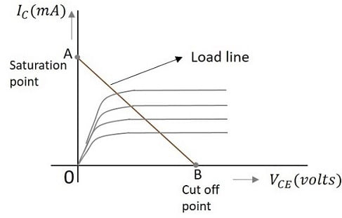
LOAD LINE :
A load line is a graphical representation used in electronics to analyze and understand the operating point of a circuit or device, particularly in the context of transistors and amplifiers. It is a visual tool that helps illustrate the relationship between voltage and current for a given electronic component. Let’s explore the concept of a load line in more detail:
Components with Load Lines:
- Transistors:
- Load lines are commonly used in the analysis of transistor circuits, both bipolar junction transistors (BJTs) and field-effect transistors (FETs).
- Amplifiers:
- Load lines are frequently employed in amplifier circuits to determine the operating point and to ensure the device operates within its linear region.
Construction of a Load Line:
- DC Load Line:
- Represents the possible DC operating points of a circuit.
- Plots the relationship between the voltage across the component (usually the collector or drain) and the current through it.
- AC Load Line:
- Accounts for the small-signal AC variations around the DC operating point.
- Illustrates the response of the circuit to small input variations.
Steps for Load Line Analysis:
- Determine DC Operating Point:
- Identify the quiescent or DC operating point of the circuit.
- This is where the transistor or device operates in the absence of an input signal.
- Plot DC Load Line:
- Use the device’s characteristics to plot the load line on a voltage-current graph.
- The load line represents all possible combinations of voltage and current that satisfy the device’s DC characteristics.
- Apply AC Signal:
- For AC load line analysis, apply a small AC signal to the circuit and observe the corresponding movement along the load line.
- Ensure Stability:
- Analyze the load line to ensure that the device operates within its linear region, providing stable and distortion-free amplification.
Significance of Load Line Analysis:
- Operating Point Stability:
- Ensures the device operates in a stable region and avoids saturation or cutoff.
- Biasing:
- Helps in selecting appropriate biasing points for transistors to achieve optimal performance.
- Amplification Quality:
- Aids in designing amplifiers with good linearity and minimal distortion.
- Understanding Device Behavior:
- Provides insights into how changes in voltage or current affect the behavior of electronic components.
Conclusion:
In electronics, a load line is a valuable tool for analyzing and designing circuits, particularly those involving transistors and amplifiers. It allows engineers to understand the operating characteristics of a device and ensures that it functions within a stable and desired range.
Explanation
Load lines load line is a tool used to find the exact value of diode current and voltage equation for load line to find the exact diode current and voltage the current through the resistor is
Id =Vs -Vd /Rs
because of the series circuit this current is the same through the diode and example if the reverse voltage is 2 volt and the resistance is 100 ampere
Id =2-Vd /100
is a linear relationship between the current and voltage if a plot this equation we get a straight line for instant let
Vd = 0 then
Id =2V-0V /100
=20mA
give the point of vertical exercise this point is called saturation because it represents maximum current across ampere let is equals to do what and this gives
Id=2V-2V/100
=0V
The point shown is horizontal axis this point is called cut off because it represent minimum or zero current the state and joining this point is called road line the cuboid the load line and a diode the point of intersection non q point represences symbol 10 years solution between the diode curve and the road line another word that you point is the only point on the graph that work for both diode and circuit by rating the condition of q point 12.5 m a diode voltage of 0.7 fault in the present discussion q is an Observation for Christmas that the equation of load line is this significance of DC load line is that every possible combination of current I and voltage in the circuit is a point that lies somewhere on the line given a particular diode pose characteristic is to find the current voltage combination that results when the diode is inserted in the circuit we can find that point by plotting the DC load line on the same i v axis that contain the diode characteristic curve the intersection of the DC local line and the characteristic curve gives us actual diode current and voltage that results when the diode is used in the circuit but we have a complaint in a fact is a graphical solution of 270 solutions.
")


 Assignment 1 Semester: Spring, 2024")
